Reverse Engineering Tears of the Kingdom's Object Rotation System
Tears of the Kingdom, the long awaited followup to Breath of the Wild, was lauded at it release for its intuitive and powerful construction system. I played Tears of the Kingdom, and while I did enjoy playing around with the build system, I couldn’t help feeling like something was strange. The problem that was on my mind the whole time was the fact that you could seemingly rotate objects in the build system by 45 degrees around 2 different axes in any order you chose, but you would only ever end up reaching a small number of possible orientations. Mathematically, this actually shouldn’t be possible.
Tears of the Kingdom Object Rotation
In Tears of the Kingdom, you can use an ability called “Ultrahand” to pick up, rotate, and stick together objects, and this can be used to build a wide variety of interactive contraptions. What we’re most interested in is the rotation part.
After grabbing an object with Ultrahand, you can rotate it. While holding the right bumper, each of the directional buttons will cause the object to rotate by a small amount around either the vertical or horizontal axis. It’s difficult to visually judge all of the rotations, but from this video, it’s pretty clear that the most easily-readable rotations are all exactly 45 degrees.
But, in the introduction, I said that this should not be mathematically possible. So, what kind of magic are they performing in Tears of the Kingdom, and why exactly is this even impossible in the first place? To find the answers to these questions, we’ll have to visit the world of group theory and discuss the concept of a finite rotation group.
Finite Rotation Groups
Rotations are an example of a type of algebraic structure called a “group”. A group is a set of elements, along with an operation that can be used to combine those elements, where the operation and the elements satisfy the following properties:
- Identity Element - There must be some element \(e\), called the identity element, such that, for any element \(x\), \(x \cdot e = e \cdot x = x\).
- Associativity - For any three elements \(a\), \(b\) and \(c\), it must be the case that \((a \cdot b) \cdot c = a \cdot (b \cdot c)\).
- Closure - The combination of any two elements of the group under the operation results in another element of the group.
- Inverses - For every element \(x\), there must be some other element \(x⁻¹\), called the “inverse” of \(x\), such that \(x \cdot x⁻¹ = x⁻¹ \cdot x = e\).
The see why rotations qualify as a group, think about measuring a 2D rotation in angles. There is an “identity” angle of \(0\) degrees. You can add two angles together to get another angle, and adding angles is associative. And, for every angle \(\theta\), there is an inverse angle \(-\theta\). So, the angular representation of 2D rotations is an example of a group. However, there are an infinite number of angles. We can also consider finite rotation groups, where only a finite number of angles are available in the system.
There are an infinite number of 2D finite rotation groups. We can define any 2D finite rotation group by picking some positive number \(N\) and dividing a full \(360\) rotation by \(N\). The resulting group would be all of the rotations at increments of \(\frac{360}{N}\).
For example, consider the case of \(N = 4\), giving you all of the rotations that you can get by rotating in increments of \(90\) degrees: \(0\) degrees, \(90\) degrees, \(180\) degrees, and \(270\) degrees, then you wrap back around to \(0\) degrees. We can combine any two angles from this set with addition that wraps around at \(360\) degrees.
| + | 0 | 90 | 180 | 270 |
|---|---|---|---|---|
| 0 | 0 | 90 | 180 | 270 |
| 90 | 90 | 180 | 270 | 0 |
| 180 | 180 | 270 | 0 | 90 |
| 270 | 270 | 0 | 90 | 180 |
\(90\) degrees is the “generating element” of this group. By starting from the identity and repeatedly combining it with the generating element, you get the entire set. For the Tears of the Kingdom rotation system, it would appear that \(45\) degree rotations around the horizontal and vertical axes would be the “generating set” of the group. So, it would seem like all we need to do would be to look for some finite 3D rotation group that features these 45 degree rotations as its generating set.
Finite 3D Rotation Groups
In three dimensions, the complexity of rotation rises dramatically, and you might assume that this would lead to a huge expansion in the variety of different rotation groups that would be available. However, this is not the case at all.
In terms of finite 3D rotation groups, you have a handful of specific rotation groups that represent the rotational symmetries of specific platonic solids.
- Tetrahedral Rotation Group
- Octahedral Rotation Group
- Icosahedral Rotation Group
And a pair of infinite families of rotation groups:
- Cyclic Rotation Groups
- Dihedral Rotation Groups
The infinite families sound promising. However, none of these represent a particularly “dense” group of rotations. These are essentially just 2D rotation and reflection groups projected into 3D space; the rotations are constrained to occur within a single plane.
If you want a finite 3D rotation group that is not limited to a single plane, you’re stuck with only the platonic solid groups, of which, the largest are either the icosahedral rotation group, which rotates around an unintuive combination of axes, or the octahedral group, which is limited to 90 degree rotations.
And that’s it. There are no more finite 3D rotation groups, but none of these support the combination of rotations that we see in the Tears of the Kingdom. This indicates that the Tears of the Kingdom rotation system is not based on a rotation group at all, and is instead using some kind of sneaky magic trick to look like a rotation group.
Spotting the Trick
So, what is this magic trick? Let’s take a look at some rotations in Tears of the Kingdom’s rotation system again, and this time, we’ll look a little more carefully.
For some combinations of starting orientation and axis of rotation, it takes 8 steps of rotation for the object to return to its original orientation:
(I’ve tracked down a shrine with cubes to make the nature of the rotations here a little easier to see.)
These combinations occur when you are rotating around an axis that passes through the centers of a pair of opposite faces or the centers of a pair of opposite edges. For these combinations, the object is rotating in exact 45 degree increments at each step.
However, for other combinations of starting orientation and axis of rotation, it only takes 6 steps of rotation for the object to return to its original orientation:
These combinations occur when you are rotating around an axis that passes approximately through two opposite corners of the cube: through the cube’s “space diagonal”.
The object appears to be rotating by 60 degrees per step around this space diagonal axis of the cube. This alone would already be proof that the rotation system is not adhering to a group structure; but, look closely. There’s also a very distinct “wiggle” as the object rotates, where the top and bottom corners move forward or backwards on each step of the rotation. If you look at the projection of the cube on the left wall, it is very clear. From this starting orientation, it is not actually rotating around the space diagonal axis passing through those opposite corners at all, because the space diagonal axis is not actually aligned with the vertical axis.
But it’s close. It’s VERY close. And this is exactly the “magic trick” we’ve been looking for. The “magic angle”, to be exact. If we imagine the cube starting from a resting position on the ground, this orientation is equivalent to lifting one corner of the cube until it is tilted at a \(45\) degree angle. However, for the top and bottom corner to be properly aligned with the vertical axis, the cube would instead need to be rotated by a special angle, coincidentally called the “magic angle”, of approximately \(54.74\) degrees.
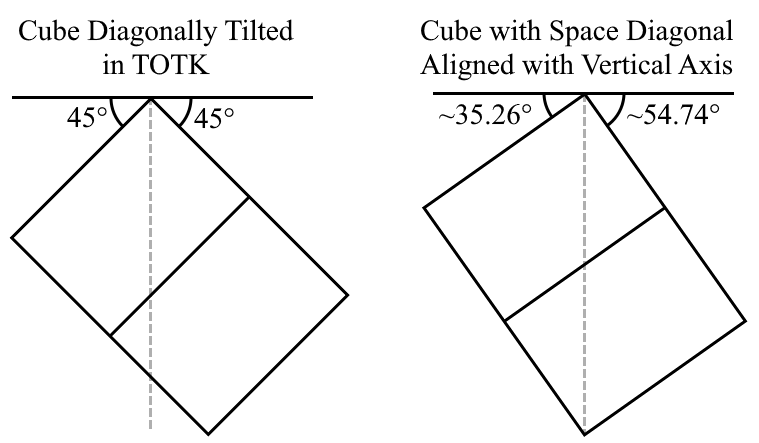
The difference is less than 10 degrees, which is difficult to spot. This illusion is aided by the fact that, when a cube is aligned in this way, the heights of its other 6 corners are staggered in a way that is visually very difficult to judge. That slight wiggle is really the only tell that there’s anything wrong here.
With the axes misaligned, the cube is essentially being rotated at each step around a tilted axis, and these long (approximately \(62.8\) degree) rotations around tilted axes are used to bridge between orientations that are neither properly aligned with one another nor spaced correctly from one another.
So, the Tears of the Kingdom rotation system doesn’t have a rotation group in it. This is even worse than what they did to Shrine Island. All joking aside, the system actually works really well in practice. Unless there happened to be a player who spent a genuinely unhealthy amount of time thinking about rotating cubes, it’s very unlikely that anyone would ever notice this behavioral quirk.
But just identifying that there is a magic trick is not the point of this post. We want to reproduce the trick. Can we reconstruct the Tears of the Kingdom object rotation system?
Constructing the Tears of the Kingdom Object Rotation System
To build our own rotation system like Tears of the Kingdom’s, we will start with the octahedral rotation group as a base. It is an extremely common rotation group for games that involve building things, such as Minecraft, because it is the rotational symmetry group of both cubes and cubic grids.
You can test out all of the reachable rotations with this little widget. The octahedral rotation group contains every rotation that can be reached by 90 degree rotations around the cardinal axes. Here, we have limited ourselves to only moving by rotating around the \(x\) and \(y\) axes, but this is still enough to reach every rotation. We can construct a \(z\) axis rotation by combining a sequnce of: a positive rotation around the \(x\) axis, a positive rotation around the \(y\) axis, then a negative rotation around the \(x\) axis. The octahedral rotation group only has \(24\) distinct rotations and isn’t nearly as granular as the Tears of the Kingdom system.
From here, we will expand the system by adding all of the 45 degree “in-between” rotations. For every pair of octahedral rotations separated by exactly 90 degrees around the \(x\) or \(y\) axis, we will add the rotation that is exactly halfway between those two rotations.
This version of the widget adds the in-between rotations, but they are restricted to only rotating towards either of the neighbors that they are “in-between”. This system expands to \(72\) distinct rotations and is fairly well-behaved, but the fact that you can’t rotate in all directions from every orientation feels a little clunky.
Since we now have an expanded set of rotations to start from, we can apply another pass of adding in-between rotations. Firstly, for any two rotations separated by \(180\) degrees around the \(x\) or \(y\) axes, we will add their \(90\) degree in-between rotation, if it does not already exist. Then, for every pair of rotations separated by \(90\) degrees around the \(x\) or \(y\) axes, we will add their \(45\) degree in-between, if it does not already exist. For now, we’ll keep the same rule about only adding neighbor connections between rotations reachable by exact \(45\) degree rotation steps to neighbors formed by inserting in-betweens.
This expands our total number of rotations to \(192\), and fills in all of our previously missing neighbors. However, some of the new rotations now have missing neighbors. Specifically, all of the rotations that have a pair of opposite corners very nearly aligned to the horizontal or vertical axis (which is the “magic trick” case discussed in an earlier section) currently cannot be rotated around that axis. To fill in these last few neighbors in the transition table, we can get away with a fairly naive approach.
Rather than looking for the specific rotation that you reach after rotating by 45 degrees and considering there to be no neighbor at all if that specific rotation does not exist, we can instead rotate by \(45\) degrees and just look for whatever the nearest rotation from the set happens to be, even if it’s not exactly the correct rotation, and just pick that rotation as the neighbor. We can compute the “closeness” of two orientations represented as quaternions by taking the quotient of the two quaternions and taking the absolute value of the quotient’s real component. The absolute value of the real component will equal \(1\) if the two are exactly equal, and will scale down to \(0\) if they are separated by a \(180\) degree rotation.
After filling in these final missing neighbors, we end up with a complete recreation of the rotation system:
If you’d like to try making use of this rotation system for some of your own projects, the rotation list and transition table can be found as a JSON file here. In this file, each rotation is represented as an array containing the 4 components of a quaternion in xyzw order, and the transition table has an entry for each rotation, storing an array of the rotation indexes of the transition targets for each neighbor direction: up, down, left, and right.
Wrapping Up
I don’t immediately have any projects myself for which this rotation system will be useful, but I hadn’t seen anyone else describing the specific way the rotations work in Tears of the Kingdom online, and I thought it was interesting. Maybe it was just so obvious that it wasn’t worth mentioning; I can’t even say with 100% confidence that this rotation system first originated from Tears of the Kingdom in the first place (though I don’t personally know of any other software that uses a system like this). But, now at least there’s a reference so that others don’t have to recalculate the rotations and the transition tables themselves.
Extra: With Three Axes
Tears of the Kingdom only allows applying rotation steps around the X and Y axes. Since since every octahedral rotation is already reachable even using only X and Y steps, it might actually seem like adding Z axis rotations wouldn’t change anything other than just improving the ergonomics of rotating things to particular orientations. However, it unexpectedly changes things quite a lot.
Adding Z axis rotations increases the total number of reachable orientations from 192 to 240. These extra rotations are put to work expanding all of the 6-cycles into 12-cycles. Each of these 12 steps is approximately \(33.68\) degrees, giving it a noticeable wobble, similar to the 6 step cycle.
The rotation list and transition table can be found as a JSON file here. In this file, each rotation is represented as an array containing the 4 components of a quaternion in xyzw order, and the transition table has an entry for each rotation, storing an array of the rotation indexes of the transition targets for each neighbor direction: up, down, left, right, clockwise, and counterclockwise.
Generating this expanded rotation system exposed some of the instability of the naive method of calculating transition tables that I used for the XY axis case. My first attempt to naively generate the table resulted in non-reflexive transitions. In other words, sometimes rotating right would transition from orientation A to orientation B, but rotating left would not return to orientation A; instead it would go to a new orientation C. It took quite a bit of finagling and two specific improvements to get the tables generated correctly:
- In the XY transition table, I rotated an orientation by \(45\) degrees in one direction, and checked for the orientation that was closest to the result. For XYZ, I do this check in both directions at once (\(+45\) degrees from start orientation to candidate end orientation, and \(-45\) degrees from candidate end orientation back towards the start orientation), and try to minimize the sum of of the error for the two checks.
- In the XY transition table, I only check at offsets of \(45\) degrees. For XYZ, I check both \(45\) and \(33.68\) degrees, and pick whichever produced the smaller error sum.
I wasn’t able to come up with a very principled basis for deciding on these rules and found them more through trial and error. I think further generalization of this rotation system, as the orientations become more dense, would require increasingly obtuse and tedious trial and error to find a valid transition table. In the worse case, you might end up having to do some kind of 3D Delaunay Triangulation in the surface volume of a 4D hypersphere, which is something I have no idea how to even approach.
Moreover, I think you get diminishing returns to a certain extent. The denser the orientations become, the harder it is for the player to know exactly what orientations are even achievable. And, since a lot of the individual rotation steps on the “in-between” orientations “wobble”, the denser the rotations get with non-octahedral rotations, the more difficult it will be for the user to actually find the right sequence of rotation steps to reach the orientation they want.
Extra: Hyperoctahedral Rotations
Trying to think about rotation in spaces with more than 3 dimensions is kind of brain-bending, but there’s actually a really simple trick to thinking about and implementing higher dimensional rotations specifically from the family of rotational symmetry groups of hypercubes, which are sometimes called “hyperoctahedral” rotation groups. In two dimensions, these are the rotational symmetries of a square; in three dimensions, a cube; in four dimensions, a tessaract, and so on.
Every hyperoctahedral rotation in any number of dimensions solely consists of:
- Permuting the axes of the coordinate system.
- Negating some number of the axes.
For example, in 2D:
- A \(0\) degree rotation involves not permuting or negating any axes.
- A \(180\) degree rotation involves not permuting the axes, but negating both.
- A \(90\) degree rotation involves swapping the axes and then negating one axis.
- A \(270\) degree rotation involves swapping the axes and then negating the other axis.
Which axes you negate in the \(90\) and \(270\) degree cases depends on the way you lay out your coordinate system, but let’s say for our examples here that \(90\) degree rotations negate the first axis (occupying the \(x\) axis’s original position) after swapping, and \(270\) degree rotations negate the second axis (occupying the \(y\) axis’s original position) after swapping. We can compactly represent these transformations with a little array syntax:
- 0 degrees: \((x, y)\)
- 90 degrees: \((-y, x)\)
- 180 degrees: \((-x, -y)\)
- 270 degrees: \((y, -x)\)
Here, each element of the array is an axis name that is potentially negated, telling you what pre-rotation vector component to put in that vector component post-rotation. This is an alternative representation I like to use for what are called “signed permutations”, a common method of representing the hyperoctahedral groups. The neat trick here is that if we represent \(x\) and \(y\) as row vectors:
\[x = \begin{bmatrix} 1 & 0 \end{bmatrix}, \quad y = \begin{bmatrix} 0 & 1 \end{bmatrix}\]And we treat our little array syntax as a column vector containing those row vectors as elements:
\[(a, b) = \begin{bmatrix} a \\ b \end{bmatrix}\]Then each of these little arrays is implicitly a matrix. For example, the \(90\) degree rotation, \((-y, x)\), becomes:
\[(-y, x) = \begin{bmatrix} -y \\ x \end{bmatrix} = \begin{bmatrix} 0 & -1 \\ 1 & 0 \end{bmatrix}\]This is actually the exact 2D rotation matrix for a 90 degree rotation. And this works in any number of dimensions.
You might notice that there are four other combinations that we haven’t listed:
- \((y, x)\) - Swap without negation.
- \((-y, -x)\) - Negate AND swap.
- \((x, -y)\) - Negation without swapping.
- \((-x, y)\) - Negation without swapping.
These four represent the four reflective symmetries of a square. In general, if we consider all possible signed permutations in a given number of dimensions, half of them will be rotations and half will be reflections, so we need some method to distinguish between the two if we want to use this concept for thinking about rotations only. The simplest trick is to make use of the parity of the permutations.
If the parity of the number of negated axes is equal to the parity of the permutation of the axes, then the signed permutation represents a rotation. Otherwise, it represents a reflection.
This all generalizes to any number of dimensions. We can represent a 90 degree rotation around the \(x\) axis in three dimensions as: \((x, -z, y)\), which corresponds to the 3D rotation matrix:
\[(x, -z, y) = \begin{bmatrix} 1 & 0 & 0 \\ 0 & 0 & -1 \\ 0 & 1 & 0 \end{bmatrix}\]We can use all of this to derive a very compact way of representing hyperoctahedral rotations for \(N\) dimensions in software. The negated axes can be represented as a \(N\)-bit bitfield, and the permutation of the axes can be represented as a permutation index from \(0\) to \(N!\). You can store both in a single integer and just use a bitshift and a bitmask to extract the two pieces. This provides a representation for both rotations and reflections, but we can choose our permutation indexing scheme cleverly to get an even more compact representation of just rotations.
If our permutation indexing scheme assigns even indexes to even permutations, and we only want to represent rotations, then we can delete one of the negation bits. We can do this because we can always recalculate it by just taking the XOR of all of the other negation bits and then XOR the result with the least-signicant bit of the permutation index. This representation can only represent rotations, and is very compact and fast to work with.